
Introduction
Radar sensors are widely used in automatic barrier gate systems to prevent the boom arm from closing on vehicles or pedestrians. This guide explains how to correctly install and wire a digital display radar sensor for anti-collision (anti-crush) protection.
What Is a Radar Sensor for Barrier Gates?
A radar sensor detects moving objects such as vehicles and pedestrians using microwave or millimeter-wave technology. When connected to a barrier gate controller, it ensures the gate remains open or reopens if an object is detected in the closing path.
Key Benefits of Using Radar Sensors
- Prevents damage to vehicles and barrier arms
- Enhances pedestrian safety
- Reduces maintenance costs
- Works without ground loop cutting
- Suitable for indoor and outdoor installations
Required Components
Before installation, prepare the following:
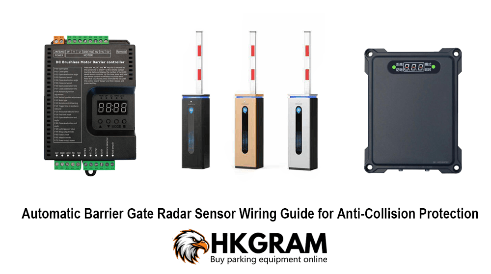
- Radar sensor (with digital display)
- Automatic barrier gate controller
- Power supply (typically DC 12V or 24V)
- Signal cables (2-core or 4-core depending on model)
- Mounting bracket and screws
Radar Sensor Wiring Overview
Most radar sensors have the following terminals:
- Power Input (+ / -): Connect to DC power supply
- Relay Output (COM / NO / NC): Used for signal control
- Ground (GND): Shared grounding